
Products


Product Features
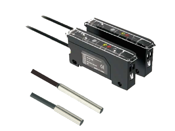
▲ Separation of amplifier and sensing head;
▲ The sensing head is as small as 2.8mm;
▲ Not limited by installation location and installation space;
▲ The detection distance is more than twice that of traditional proximity sensors, with a maximum detection distance of up to 7mm.
▲ The sensing head is as small as 2.8mm;
▲ Not limited by installation location and installation space;
The detection distance is more than twice that of traditional proximity sensors, with a maximum detection distance of up to 7mm.
Application examples
Detecting the speed of gears
Detecting small metal blocks
Component Name
Usage Guide
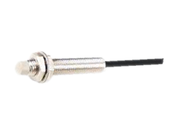
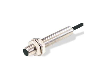
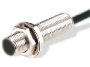
Cylindrical type
Fix the sensing head with screws at a distance of 5mm or more from the tip of the sensing head (locking torque: maximum 2N · m).
Please fasten GX-402 on metal parts that are 15mm or less away from the tip.
Threaded type
When installing the threaded sensing head, do not tighten it with a torque greater than the one shown in the table below.

connection
Connect the sensing head and amplifier with a high-frequency coaxial line. The extension length is limited to 10m (5m for GX-302 and GX-402).
Environmental Metals
Embedded sensors can be directly installed inside metal bases, while non embedded sensors must be installed according to the instructions in the table to reduce interference caused by metal environments.
interfere
(1) Anti interference operation mode switch setting
Do not set the anti-interference operation mode switch of two adjacent GN-A1 to the same mode,
As shown in the following figure:

(2) Sensor head
When installing two or more sensors of the same model face-to-face or in parallel, they should be isolated according to the distance listed in the table below to avoid interference.
Note:
The data shown in the table above is when the regulator is adjusted to the stable detection position. Within parentheses
The value is the data obtained when using an anti-interference converter in parallel with the sensing head.
Connection of sensing head
1. Modify the front end of the sensor cable. And confirm that the buried wire and wire core are twisted tightly separately.
*When the coating is peeled off, the buried wire is wrapped around the wire core. Before modifying the sensor wire, the buried wire and wire core should be separated first.
2. Loosen the fastening screws of the wiring board counterclockwise.
3. Insert the sensor directly into the insertion interface of the amplifier, and confirm that the buried wire and wire core are inserted into the correct interface, and that the sensor wire is not twisted.
4. Tighten the fastening screws of the terminal block clockwise, with a tightening torque not exceeding 0.15N · m.
5. Start the amplifier and confirm that the unconnected alarm output is in the OFF state. If the indicator light is ON, you must return to step 1 and repeat the operation.
adjustment
Both NEAR-ON and NEAR-OFF modes can be applied
The NEAR-ON mode uses a normally open relay that closes when a target object is detected. The NEAR-OFF mode uses a normally closed relay that opens when a target object is detected.
NEAR-ON operation
When positioning the target object, rotate the adjuster clockwise and locate point A where the output indicator light has just turned on. If the output indicator light is on, rotate the regulator counterclockwise.
2. Move away the target object, rotate the adjuster clockwise again and find point B where the output indicator light is on.
NEAR-OFF operation
When positioning the target object, rotate the regulator clockwise and locate point A where the output indicator light is off. If the output indicator light has turned off, rotate the regulator counterclockwise.
2. Move away the target object, rotate the regulator clockwise again and find point B where the output indicator light goes out.
3. Set the regulator to the middle position between point A and point B. Output when the output indicator light is on
| appearance |

|
|
| Power Supply | 12 to 24VDC, maximum pulsation (P-P) 10% | |
| Current/power | Maximum 25mA | |
| reaction time | Maximum 1ms | |
| Temperature fluctuations | When the temperature is within the range of 0 to 55 ℃, it is ± 8% of the detection distance at 23 ℃ | |
| sensitivity modulation | 25 turn rotary knob regulator | |
| Output mode | N. 0./N.C optional switch | |
| t PI DAR | Optional 10ms delay/timer off | |
| Control output | NPN (PNP) collector open circuit maximum 100mA (maximum 40V/PNP 26.4V) residual voltage maximum V | |
| Alarm output not connected | NPN (PNP) collector open circuit maximum 100mA (maximum 40V/PNP 26.4V) or less, residual voltage maximum 1V | |
| protection circuit | Power reverse connection protection, output overcurrent protection, output surge protection | |
| ambient temperature | 0 to 55 ℃ | |
| relative humidity | 35% to 85%, no condensation | |
| weight | About 57g | |
| model | NPN | GN-A1 |
| NPN | GN-A1P | |
| type | Embedded type | ||||||
| Cylindrical type | Threaded type | Ultra-thin type | Thin type | ||||
| model | GX-302 | GX-305 | GX-308 | GX-110 | GX-114 | GX-605 | GX-614 |
| Stable detection range | 0 to 0.6mm | 0 to 1mm | 0 to 2mm | 0 to 5mm | 0 to 1mm | 0 to 5mm | |
| Maximum detection distance | 1.2mm | 3mm | 5mm | 8mm | 3mm | 8mm | |
| Detectable object | Black metal (see characteristics of non-ferrous metals) | ||||||
| Detection target object (iron: 1mm) | 5×5mm | 10×10mm | 15×15mm | 5×5mm | 15×15mm | ||
| Repetitive accuracy | 0.002mm | 0.005mm | 0.002mm | 0.005mm | |||
| movement differential | 0.04mm | 0.05mm | 0.04mm | 0.05mm | |||
| Temperature fluctuations | ± 10% of the detection distance at 23 ℃ (GX-402: ± 30%, maximum -10%); GX-302/305;- 10% to 20%) at a detection distance of ± 10% (GX-402: ± 30% maximum -10% within the range of -10 to 60 ℃) at 23 ° C | ||||||
| Protection level | IP67 | ||||||
| ambient temperature | -10 ℃ to 60 ℃, no freezing | ||||||
| relative humidity | 35% to 85%, no condensation | ||||||
| weight | About 30g | About 45g | About 47g | About 58g | About 65g | About 32g | About 60g |
| type | Embedded type | Non buried type | ||||
| Oil resistant type | Cylindrical type | Threaded type | Cylindrical type | |||
| model | GX-108 | GX-305s | GX-308s | GX-110s | GX-402 | GX-422 |
| Stable detection range | 0 to 1.5mm | 0 to 1mm | 0 to 2mm | 0 to 3mm | 0 to 9mm | |
| Maximum detection distance | 2.5mm | 3mm | 5mm | 7mm | 18mm | |
| Detectable object | Black metal (see characteristics of non-ferrous metals) | |||||
| Detection target object (iron: 1mm) | 10×10mm | 5×5mm | 10×10mm | 25×25mm | ||
| Repetitive accuracy | 0.005mm | 0.002mm | 0.005mm | 0.002mm | ||
| movement differential | 0.07mm | 0.04mm | 0.05mm | 0.06mm | ||
| Temperature fluctuations | ± 10% of the detection distance at 23 ℃ (GX-402: ± 30%, maximum -10%); GX-302/305;- 10% to 20%) at a detection distance of ± 10% (GX402: ± 30% maximum -10%) within the range of -10 to 60C | |||||
| Protection level | IP67 | |||||
| ambient temperature | -10 ℃ to 60 ℃, no freezing | |||||
| relative humidity | 35% to 85%, no condensation | |||||
| weight | About 52g | About 82g | About 88g | About 115g | About 29g | About 180g |
|
Note 1: GX-305S 、GX-308S 、GX-110S For the type of embedded with spiral tube;GX-305 、GX-308 、GX-110 For non spiral buried type; 2:1M: Line length 2m .2M:Line length 5m.3M: Line length 10m. |
||||||


|
DIKC Separated Proximity Sensor GN Series |
|

Follow WeChat

 Home
Home


 Official website
 13570894005
 E-mail